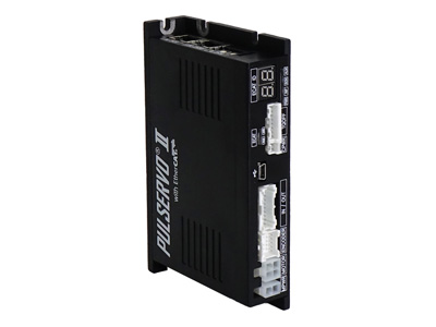
EtherCAT type driver
 Please purchase the driver with a motor as a set, as it requires unique settings such as the current, etc. for the motor.
Specifications
| Applicable motor | PSM2-20 series | PSM2-28 series | PSM2-42 series | PSM2-56 series | PSM2-60 series |
|---|---|---|---|---|---|
| Driver model | PSD2-EC-20 series | PSD2-EC-28 series | PSD2-EC-42 series | PSD2-EC-56 series | PSD2-EC-60 series |
| Input voltage | 24VDC ±10% | ||||||||||
|---|---|---|---|---|---|---|---|---|---|---|---|
| Control method | Closed loop control by 32-bit MCUs | ||||||||||
| Power consumption | 500 mA Max (except Motor current and Brake current (when brake is used)) | ||||||||||
| Environmental specifications | Temperature | Ambient operating temprature: 0 to 50 °C (No condensing) Ambient storage termprature: −20 to 70 °C (No condensing) |
|||||||||
| Humidity | Ambient operating humidity: 35 to 85 %RH (No condensing) Ambient storage humidity: 10 to 90 %RH (No condensing) |
||||||||||
| Shock resistance | 0.5G | ||||||||||
| Applicable standards | CE marking: EN61800-3:2004/A1:2012 (EnvironmentⅡC3) RoHS directive: 2011/65/EU (2015/863/EU is included) |
||||||||||
| Functions | Rotating speed | 0~3,000rpm | |||||||||
| Resolutions |
|
||||||||||
| Protection functions (Error output) |
Overcurrent, Over-speed, Position tracking, Overload, Overheat, Regenerative voltage, Motor connection, Encoder connection, Main power-supply voltage, In-position, ROM, Excessive positioning error, Torque-Off circuit Note: Contents can be checked by Error Code(603Fh) and Error Code chart. |
||||||||||
| LED displays | Power supply, In-position, Excitement On status, Alarm | ||||||||||
| EtherCAT | Supporting Communication protocols | CoE (CANopen application protocol over EtherCAT), FoE (File Access over EtherCAT) |
|||||||||
| Supported profile | CiA402 drive profile | ||||||||||
| Operation Modes | Cyclic Synchronous Position Mode ※1 Profile Position Mode, Homing Mode |
||||||||||
| Synchronous mode | Free Run, SM Event, DC SYNC Event (250 µs or more) | ||||||||||
| Input/ output signal |
Input signal features | + Side end limit input, - Side end limit input, Origin input, Torque Off input Six General-purpose input signals Interface:Photo-coupler input |
|||||||||
| Output signal features | Torque Off status output, Brake output, five General-purpose output signals Interface:Photo-coupler output |
||||||||||
※1 The operating mode may also be abbreviated as follows.
CSP mode:Cyclic Synchronous Position Mode
PP mode:Profile Position Mode
HM mode:Homing Mode
CSP mode:Cyclic Synchronous Position Mode
PP mode:Profile Position Mode
HM mode:Homing Mode
External dimensions
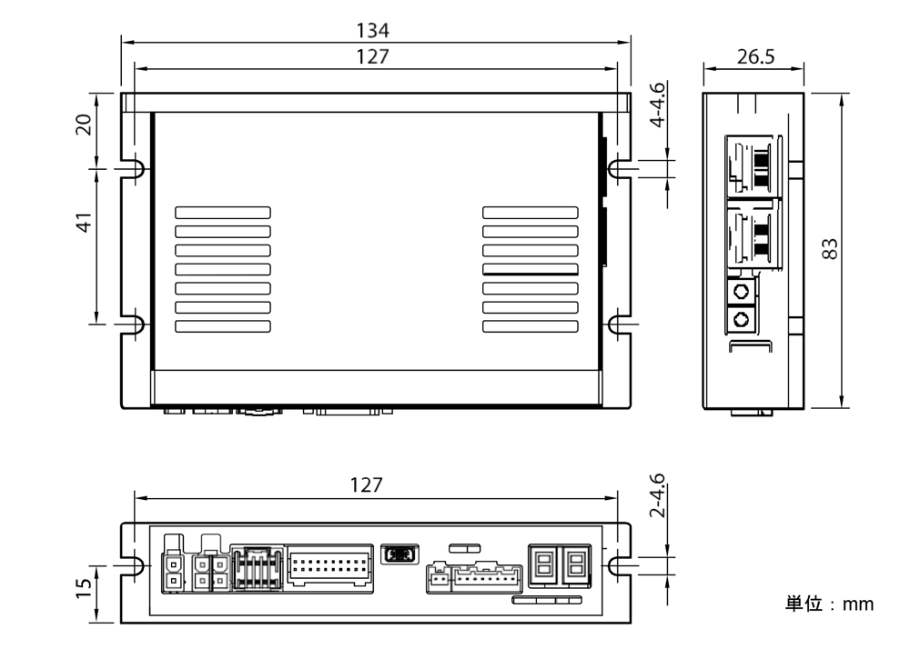
*Click to zoom in.
System configuration
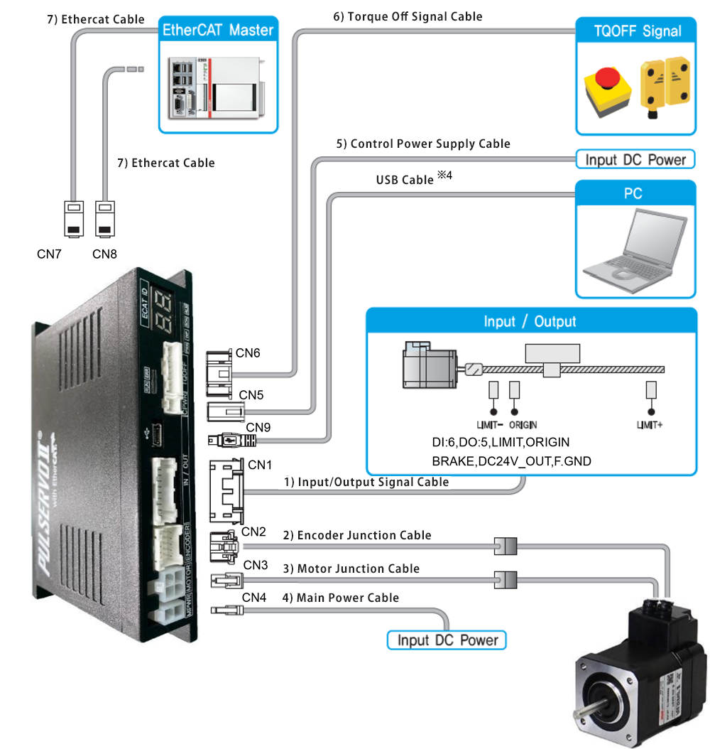
*Click to zoom in.
Input / output signal (CN1)
| Pin No. | Function | Input / output |
|---|---|---|
| 1 | LIMIT+ | Input |
| 2 | LIMIT- | Input |
| 3 | ORIGIN | Input |
| 4 | Digital In1 | Input |
| 5 | Digital In2 | Input |
| 6 | Digital In3 | Input |
| 7 | Digital In4 | Input |
| 8 | Digital In5 | Input |
| 9 | Digital In6 | Input |
| 10 | Digital Out1 | output |
| 11 | Digital Out2 | output |
| 12 | Digital Out3 | output |
| 13 | Digital Out4 | output |
| 14 | Digital Out5 | output |
| 15 | BRAKE+ | output |
| 16 | BRAKE- | output |
| 17 | EXT GND | Input |
| 18 | EXT DC24V | Input |
| 19 | F.GND | - |
| 20 | F.GND | - |