There are various types of stepping motor ICs from semiconductor companies. When selecting a drive IC, there are some key specifications besides the basic specifications such as unipolar/bipolar drive and the drive current value.
This section explains the specifications of signals that give operation commands to a stepping motor drive IC.
Command input interface
 To drive a motor, you need to switch the excitation sequence of each phase of the motor coil.
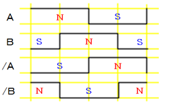
By switching the motor-coil current of each phase in accordance with a fixed sequence, the excitation (N/S polarity) is switched, and the motor rotates.
(The following figures show an example of 2-2-phase excitation.)
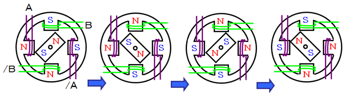
Enter the command to a drive IC to switch this excitation sequence when driving a motor.
Typical type of command inputs
a. Clock (=Pulse) input type
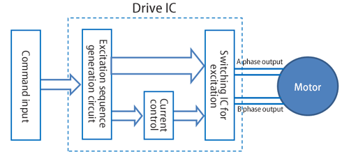
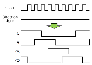 You can control a motor using two types of signal: clock and direction. A drive IC converts the clock and direction signals into the excitation sequence of each phase in an internal circuitry to drive a motor.
The excitation sequence switches when the clock changes. The motor speed is controlled by the clock speed, the motor rotation amount is controlled by the number of clocks, and the motor rotation direction is controlled by high/low of the direction signal.
In a micro-step drive with a micro-step compatible drive IC, you can perform a micro-step drive with only using clock and direction signals without considering the excitation sequence.
| Advantages | Easy software control with two types of signal: clock and direction. |
|---|---|
| Disadvantages | If the clock-line wire is routed to straddle the boards, there is a possibility of malfunction due to noise. A filter may be inserted in the signal input section of a driver. |
b. Phase input type
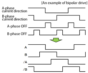 The level signals that control the excitation status such as the direction of current, excitation ON/OFF, and the current ratio of each phase of a motor coil, generates the required excitation sequence to control a motor.
Motor speed, rotation amount, and rotation direction are controlled by the switching order of the excitation sequence and the switching speed.
When performing a micro-step drive with a micro-step compatible drive IC, several signals to control the current ratio are required in addition to the signals shown in the figure below.
| Advantages | Since the excitation sequence status is provided by level signals, it is hard to malfunction even if noise is placed. |
|---|---|
| Disadvantages | The number of command signal increases depending on the excitation method: 2-2 phase excitation: two lines, 1-2 phase excitation: four lines, and W1-2 phase excitation: six lines. In addition, the excitation sequence must be generated by the control software. |
c. Serial input type
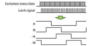 To control a motor, the excitation status data such as the excitation sequence, which is similar to the phase input, is input to a drive IC using two to three serial communication signals.
Motor speed, rotation speed, and rotation direction are controlled by the excitation sequence switching order and its switching speed.
When performing a micro-step drive with a micro-step compatible drive IC, the current ratio data is also input via communication in addition to the excitation sequence.
| Advantages | Since the excitation sequence is written repeatedly by serial communication, it is hard to malfunction even if a noise is placed or routing is long. In addition, the number of command signals is as small as about two or three. |
|---|---|
| Disadvantages | The control software needs to be complicated to generate the excitation sequence and also to perform a serial communication. Also, this type cannot operate at a very high speed because it uses simple communication. |
*In addition, some drive ICs have built-in control functions, so that you can input operation commands directly to them.
*The clock input signal is generated by a CPU, but it may be difficult to set fine clock frequencies or to perform smooth speed change
Mabuchi Motor NPM offers the dedicated clock(=pulse) generation LSIs, [PCL series] and [PCD series] which can manage these detailed settings.
[PCD Series] can also generate excitation sequences (2-2 phase and 1-2 phase) for phase input.
INDEX
- 1.Fundamentals of stepping motor drive IC
- 2.Specification of the signal that gives operation commands to a drive IC
- 3. Drive IC control method "Excitation mode"
- 4. Decay control
- 5. Current setting when using constant-current drive ICs
- 6. How to select a motor to drive with a constant-current drive IC
- 7. Heat generation of a motor and a driver
- 8. Acceleration and deceleration of stepping motors
- 9. Malfunctions of stepping motors