When more motor power (=torque) is required, it is increased by applying larger current. However, the heat generation can increase at the same time.
This section explains the image of motor and drive IC heat generations.
1. Heat generation of a motor
Copper loss: P = Power loss (I2R) generated from the winding resistance of a motor coil and the current flowing.
Iron loss: Loss due to magnetic field and its change. There is the loss due to hysteresis and the loss due to eddy currents generated in magnetic body by a change in magnetic field. Eddy current loss is generated on the same principle that an electromagnetic cooker (=microwave oven) generates heat in a cooking appliance. In a motor, Eddy current loss can be reduced by piling up thin iron plates (laminated steel plates).
Machine loss: Loss due to the friction or air resistance in a motor. The ratio is small.
The ratio of machine loss is rather small among these losses, and iron loss becomes remarkable when rotating medium-sized to large-sized motors, which might require laminated steel plates, at high speed.
For miniature motors such as PM type in NPM, copper loss accounts for a large part of heat generation.
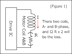 The copper loss of a stepping motor is the electric power loss generated from the resistance component R of a motor coil and the current flowing through. However, since a stepping motor has two coils, A-phase and B-phase, the electric power losses from the two coils become heat. *1
[PCLOSS = (I2 × R) × 2] [Figure 1]
In addition, the allowable electric power that a motor can tolerate is almost determined by the size, and the allowable electric power can be inferred roughly from the rated voltage and the winding resistance of a motor.
[PMOTOR ≒ (V2 ÷ R) × 2]
However, this allowable electric power can cause the motor surface temperature high if not radiating heat, so this temperature issue must be considered.
Heat radiation and current reduction are effective in suppressing heat, especially, power is proportional to the square of a current, so reducing the current to 70% would result in the heat about 1/2, and halving the current would result in the heat about 1/4.
*1
In 2-2 phase excitation, the current is applied to two coils: A-phase and B-phase.
In 1-2 phase excitation, the current flows switch through one coil and two coils by turns.
In micro-stepping, current flows through two coils, but the ratio of current changes so the calculation with effective current is closer.
2. Heat generation of a drive IC
 Most of the heat out of a drive IC is generated in the power element.
FET: Resistance value between the drain and source when FET is ON and power loss (P = I2R) generated from the current flowing.
Transistor (bipolar): Power loss (P=VI) generated from the collector-emitter voltage and current.
Diode: Power loss (P=VI) generated from the forward voltage and the forward current of a diode.
Also, switching loss can cause heat generation. [Figure 2]
FET ON resistor becomes as low as around 0.1 to 0.4 Ω in recent years, and most of drive ICs use FET elements.
For example, when a current of IM=1A is applied, assuming that the saturation voltage of the collector-emitter voltage of a transistor: VCE = 0.6V and FET ON resistor: RDS = 0.2 Ω,
Transistor loss: 1A × 0.6 V = 0.6 W,
FET loss: 1A2 × 0.2 Ω = 0.2 W
Now, FETs are getting more used because the power loss is lower. *2
In the past, regenerative current was regenerated through a diode in parallel with a FET, however, recently more ICs are getting more used to reduce the loss by passing regenerative current through a FET by turning with less loss than the power loss (P= VF × I)F of a diode during regeneration. [Figure 3]
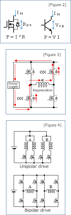
Drive ICs consist of unipolar and bipolar drives. When calculating the power loss in bipolar drives, you must calculate it by the combined resistance of ON resistance of upper and lower FETs through which the current passes [Figure 4]. Since there are two coils of A phase and B phase, the power loss for two circuits becomes heat in both drive ICs.
[PLOSS = (I2 × RDS) × 2]
The allowable heat generation by a drive IC is determined by the power dissipation (W) considering the derating of the IC specifications, and is calculated from the operating temperature, ambient temperature, heat dissipation conditions, etc. At the end, you will operate the motor under various conditions and measure the temperatures to judge the validity. *3
Similar to motors, heat dissipation and current reduction are effective in reducing heat in a drive IC. Heat generation will be about 1/2 when the current is down to 70% and about 1/4 when the current is halved.
*2 Because the power is proportional to the square of a current, transistors may be advantageous for high currents, such as using a IGBT.
*3 A drive IC has the target motor current, and it may be difficult to adjust the such current when driving a small-current motor with a large-current drive IC. In such a case, we recommend confirming with the IC manufacturer beforehand.
INDEX
- 1. Fundamentals of stepping motor drive IC
- 2. Specification of the signal that gives operation commands to a drive IC
- 3. Drive IC control method "Excitation mode"
- 4. Decay control
- 5. Current setting when using constant-current drive ICs
- 6. How to select a motor to drive with a constant-current drive IC
- 7. Heat generation of a motor and a driver
- 8. Acceleration and deceleration of stepping motors
- 9. Malfunctions of stepping motors