 This section describes the malfunctions of stepping motors that are not directly related to the drive ICs.
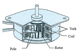
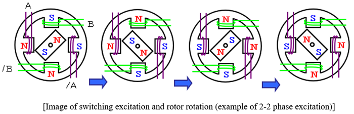
A stepping motor rotates by switching the excitation of the electromagnets in the stator in order and then the permanent magnets of the rotor are attracted and repelled. The rotation is in synchronization with switching the excitation of electromagnets.*1
When operating a motor, we assume that the rotor position is in synchronization with the excitation of electromagnets. However, in certain conditions, the synchronization may be lost because the rotor cannot follow the excitation switching. This section explains the malfunctions which occur under the certain conditions.
*1 Permanent magnet is not used for the rotors in VR type stepping motors. The motors rotate only with attraction power.
1. Movements of the rotor of a stepping motor
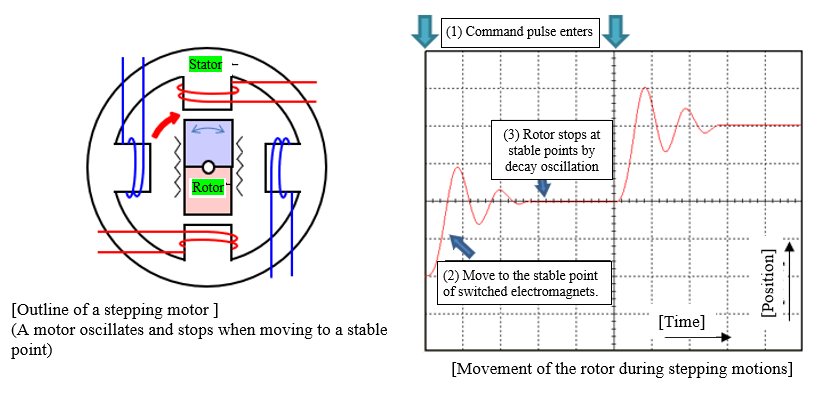
The rotor of a stepping motor rotates by attracting and repelling of the electromagnets in the stator, so the rotor stops at stable points by decay-oscillation when moving one step at a time. The oscillation varies with the motor size, coil winding, excitation current, excitation method, rotor inertia, viscosity/inertia of the load, and the like.
When rotating at high speed, the next command pulse can enter before the decay oscillation occurs, and the rotor will not be affected by the oscillation.
2. Stepping motor “Out-of-step”
 As described earlier, a stepping motor rotates in synchronization between the switching of the electromagnets in the stator and the permanent magnets in the rotor. If the excitation switching of the electromagnet is sadden or the switching speed is too fast, the rotor may not follow the excitation switching, and the synchronization cannot be made. This is called “out-of-step.”
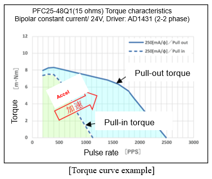
The speed at which a motor can start in synchronization with input pulses at fixed rate is called “Starting pulse rate”. Above that rate, the rotor cannot follow the excitation switching of the electromagnet, resulting in out-of-step. If you want to operate within the pull-out torque range higher than the starting pulse rate, start within the pull-in torque range and then accelerate, so that the rotor can follow. *2
At speed exceeding the pull-out torque range, the rotor cannot follow the excitation switching speed of the electromagnets, resulting in out-of-step. In such a case, use countermeasures such as 1) use a motor that can rotate at a higher speed, 2) increase the motor voltage, or 3) adjust the motor current. *3
*2 “Pull-in torque” is the torque curve representing the relationship between the starting pulse rate and the load torque. A torque curve representing the relationship between the pulse rate and the torque that allows synchronization operations is called “Pull-out torque”. Refer to "1. Pull-in torque and pull-out torque" in No. 8 article, “Acceleration and deceleration of stepping motors”.
*3 If the motor current is raised, the force to stop at the stable points may become a brake. Therefore, lowering the motor current may rotate the motor faster in some cases.
3. Disturbance of stepping motors
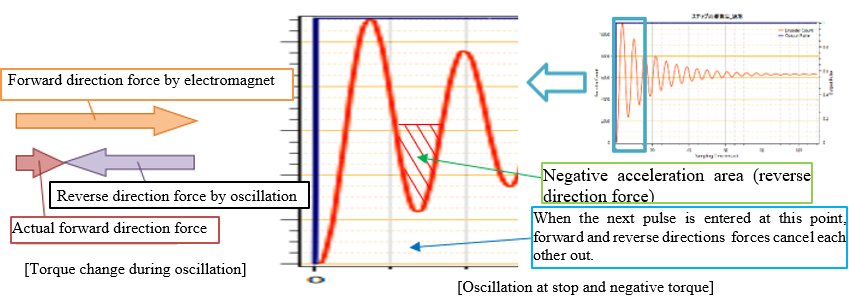
If the next pulse signal is entered while a rotor is still oscillating, the force to rotate in the forward direction and the force to rotate in the reverse direction caused by the oscillation may collide and cancel each other out. Depending on the load conditions or the natural frequency of a motor, the rotor may not move properly to cause displacement of the rotor position. This is called “disturbance.” The pulse frequency at which the disturbance occurs has a certain width, and the frequency band is called “disturbance range.”*4
In many cases, the disturbance range is 250 pps or less in permanent magnet motors and 500 pps or less in hybrid motors in 2-2 phase excitation (basic step).
Countermeasures against disturbance include 1) avoid the disturbance range, 2) reduce the drive current, 3) use micro-step drive, and 4) install a damper. *5
*4 Sometimes, the disturbance range is also referred to as "resonant area" or "resonant frequency". A phenomenon that a motor in that band area cannot rotate properly is called "disturbance".
*5 2) and 3) reduce disturbance by reducing oscillation when stopping. Also, when a load is applied, the viscosity of the load may be the damper and prevents disturbance from occurring.
4. Reverse rotation of stepping motors
When conditions such as large load inertia, operating speed, and rotor oscillation are combined, a motor may rotate in reverse direction if any external force in reverse direction is applied.
In a stepping motor, the permanent magnet in the rotor rotates by attracting and repelling in synchronization with the excitation switching of the electromagnet in the stator.
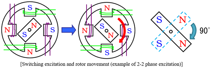
When proceeding in one step with 2-2 phase excitation, the rotor moves from the original excitation stable point where the magnets attract each other to the next excitation stable point as shown in the figure below.
In a normal operation, the rotor moves 90 degree of an electric angle before and after switching the excitation.
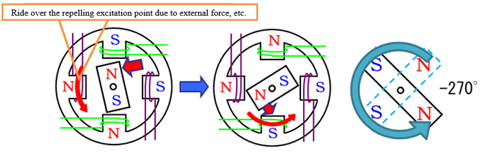
However, if any force in the reverse direction is applied to the load with a large inertia due to a collision or other reason, the rotor may move in the reverse direction toward the next excitation stable point after riding over the repelling excitation point*6. If this happens, the rotor will move by -270 degree of an electric angle.
If the conditions such as load inertia, rotor oscillation, and pulse-input speed are combined, the motor rotates in the reverse direction at a speed three times faster than the normal operation by continuously riding over the repelling excitation points.*7
Countermeasures for reverse rotation include:
1) reduce the load inertia
2) change the operating speed
3) adjust the motor current value
4) use a motor whose pull-in torque is larger than the external force
5) avoid the disturbance range to operate
Also,
6) use an excitation method such as 1-2 phase or micro-step excitation, where the distance between the multiple stable points are short.
Stepping motors can perform position and speed controls without any feedback control, however, there are some disadvantages we have mentioned. So, we hope you will understand them well and use the motors under appropriate conditions.
*6 Reverse rotation is often triggered by repelling due to pushing harder than necessary or hard-stop by hitting to the mechanical ends. When pushing, it is necessary to confirm the actual measurement of the pushing stroke and set the stop position where no large repelling torque is applied.
*7 The rotor should have moved 90 degree per pulse, but it actually moves 270 degree per pulse, which moves three times faster.
INDEX
- 1. Fundamentals of stepping motor drive IC
- 2. Specification of the signal that gives operation commands to a drive IC
- 3. Drive IC control method "Excitation mode"
- 4. Decay control
- 5. Current setting when using constant-current drive ICs
- 6. How to select a motor to drive with a constant-current drive IC
- 7. Heat generation of a motor and a driver
- 8. Acceleration and deceleration of stepping motors
- 9. Malfunctions of stepping motors