1. Constant-current drive method for stepping motors
 The constant-current drive circuit that is inside a motor driver operates in the following way: See [Figure 1] and [Figure 2].
The winding of a stepping motor is also a coil, so the rated-current drive utilizes the property.
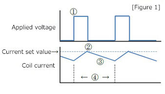
(1) Turns ON the switching element (FET, etc.) to apply voltage from the power supply to the coil, so that the coil current is increased. ※1
(2) When the current reaches the set value, turns OFF the switching element to stop the voltage supply from the power supply.
 (3) The energy stored in the coil is consumed by commutating the current through the path which can pass. At this time, the current flowing through the coil decays because the energy is consumed.
(4) Repeats the steps (1), (2), and (3) above at regular intervals to control the current flow constant.
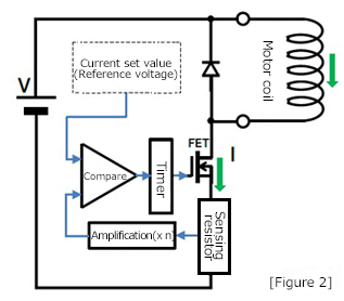
A current sensor is required to determine whether or not the current has reached the set value in (2). However, in many drive ICs, an inexpensive resistor is used as the current sensor (sensing resistor).
According to Ohm's law (V = I × R), when any current is applied to the resistance, voltage is generated at both ends of the resistor. Therefore, the value of current flowing through the coil is determined by measuring this voltage.
If a resistance is inserted in series with the motor coil, the current through the coil also flows through the resistance. By measuring the voltage at both ends of the resistance, you can determine the current value.
※1 The coil of a motor has an inductance that serves to prevent changes in current.
The characteristics of this inductance (induced electromotive force) is utilized when you control the current of a motor.
・If you apply voltage while no current flows through a coil, the current increases gradually over time.
・If you stop applying the voltage while current is flowing through a coil, the current flows through the path available inside the circuit due to the energy stored in the coil. If there is no path available which current can pass through, a high voltage can be generated at the coil end and the circuit may be damaged.
2. Reference voltage setting and sensing resistor selection
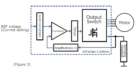
Please note that if the value of a sensing resistor is large, a large wattage resistor is required. Therefore, a circuit to amplify the sensing voltage is built in a drive IC so that a small wattage resistor can be used. [Figure 3] ※2
For an example, we select the reference voltage and sensing resistor under the following conditions.
・REF voltage input range of a drive IC: 0.8 to 2 V
・Drive IC sensing voltage amplification: 5 times
・Current applying to a motor coil: 0.5 A
Selection procedures:
(1) Since REF voltage = 0.5A × sensing resistor R × 5 times, assuming that REF voltage is 2 V, determine the assumed sensing resistor R'. This results in R' = 0.8 Ω.
(2) Select a resistance value smaller than 0.8 Ω from available resistance values such as E24 series so that REF voltage does not exceed 2V. In this example, R = 0.75 Ω is selected.
(3) Select a resistance of 0.1875 watt or higher according to I2 × R. In this example, 0.5 watt is selected.
(4) According to R = 0.75 Ω, REF voltage = 1.875 V.
As the result, the reference voltage of 1.875 V and sensing resistor of 0.75 Ω (0.5W) are selected. ※3
The reference voltage can be determined by dividing a stable voltage into resistors or by using the DA output voltage of a microcomputer.
You can adjust the current value by setting a variable resistor for the resistance voltage divider. Please note, however, that the voltage should never exceed the REF voltage input range of the drive IC. ※4
※2 Some drive ICs have the level-conversion circuit for micro-steps or current-ratio adjustments, some have the built-in sensing resistor, and some ICs have sensing resistors mounting in the power supply side.
※3 In setting constant-current drive, both reference voltage and sensing resistor are the keys. When designing a driver board, make sure to stabilize the reference voltage as well as to place and connect the sensing resistor at a low impedance near the drive-IC.
※4 An error can occur in the current value flowing through a coil due to the variations in the sensing resistors, the amplifier circuit, and the coil specification.
INDEX
- 1. Fundamentals of stepping motor drive IC
- 2. Specification of the signal that gives operation commands to a drive IC
- 3. Drive IC control method "Excitation mode"
- 4. Decay control
- 5. Current setting when using constant-current drive ICs
- 6. How to select a motor to drive with a constant-current drive IC
- 7. Heat generation of a motor and a driver
- 8. Acceleration and deceleration of stepping motors
- 9. Malfunctions of stepping motors