Linear Shaft Motor - The Next Generation Actuator
 Nippon Pulse's family of Linear Shaft Motors are the next generation linear brushless motor. When reliability, zero maintenance, zero cogging and precision are paramount, the Linear Shaft Motors from Nippon Pulse are an ideal component choice, offering the user uncompromised performance, ease of use, compact package size and high value.
What is a Linear Shaft Motor?
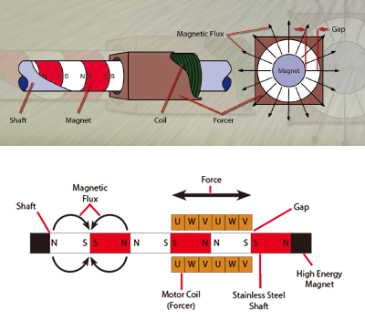
The Linear Shaft Motor is a high precision direct drive linear servomotor consisting of a shaft of rare Earth-Iron-Boron Permanent Neodymium Magnets and a “forcer” of cylindrically wound coils which can be supplied with optional Hall effect devices. The shaft supplies the magnetic field which the forcer acts upon. The forcer assembly, combined with the amplifier and control electronics, produces the force for the motor. The Hall effect devices can be supplied, if they are required by your selected servo driver for proper commutation of a brushless linear motor, and are integrated into the forcer assembly.
 The Linear Shaft Motor was designed with three basic design concepts:
- Simple - High Precision - Non Contact -
Linear Shaft Motors are simple. They consist of only two parts, a magnetic shaft and a “forcer” of cylindrically wound coils.
Linear Shaft Motors provide ultra-high precision. They have no iron in the forcer or shaft for precision and zero cogging. The coils of the Linear Shaft Motor form the core, providing the stiffness expected in an iron-core motor.
Linear Shaft Motors are non-contact. Since the coil completely wraps around the magnets, all the magnetic flux is efficiently used. This allows for a large (0.5 to 5.0mm) nominal annular air gap. This air gap is non-critical, meaning there is no variation in force as the gap varies over the stroke of the device.
Basic Structure of a Linear Shaft Motor
The magnetic structure of the Shaft is built in such a manner that there is no space between each magnet; it is fully supported within itself. The magnetic structure is then inserted into a protective stainless-steel tube. This process is protected by numerous patents. This patented process produces a very strong magnetic field twice that of other linear motors.
Features of Linear Shaft Motors
• Quiet — due to the absence of friction, the only mechanical contact section is the linear guide
(Fully non-contact operation is possible using an air slider)
• Simplified unit construction allows a stroke of up to 4.6 meters
• High speed drive (greater than 10m/s)
• Low speed drive (8μm/s)
• Allows for parallel drive using only one encoder and one driver
• Virtually no speed fluctuation (±0.006% at 100mm/s)
• Durable construction, capable of operation even underwater or in a vacuum
Line Up
Some sizes are not listed. Please contact us.
Standard Models
Large Gap Models
Baby Shaft Models
Applications
Friction-free and quiet
The Linear Shaft Motor's moving parts are all non-contact. All sources of noise and friction are liminated, allowing use in quiet surroundings, such as test laboratories and medical facilities.
No speed fluctuation
Ideal for constant speed drug dispensing, which may be difficult to achieve with lead-screw or ball-screw systems.
Environmental compatibility
Operates well in a vacuum and in production locations where oil or water are factors.
Large stroke lengths
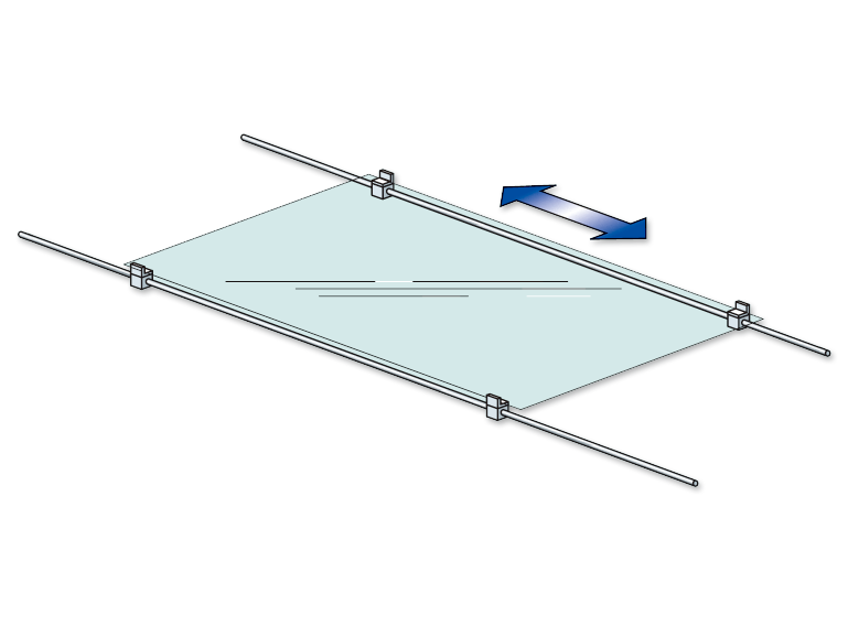
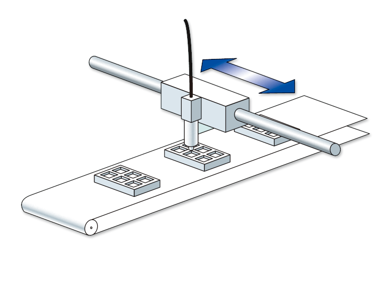
Stroke lengths up to 4.6 meters. Ideal for high-precision conveying, such as LCDs over relatively long distances.
High controllable speed
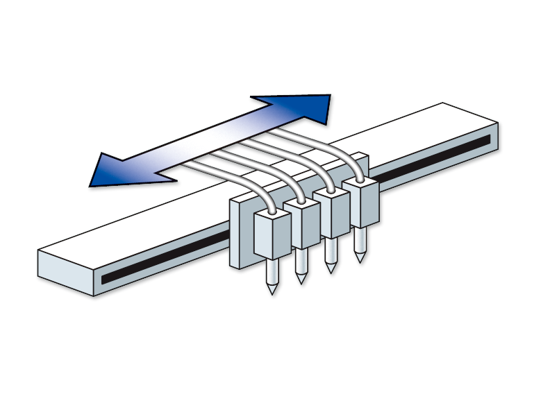
Speeds greater than 10 meters/second have been documented. Ideal for line head drives in high-speed printers.
Low speed drives
Speeds as low as 8μm/second have been documented. Ideal for equipment that may be difficult to handle with ball-screws, such as life sciences equipment.
High resolution
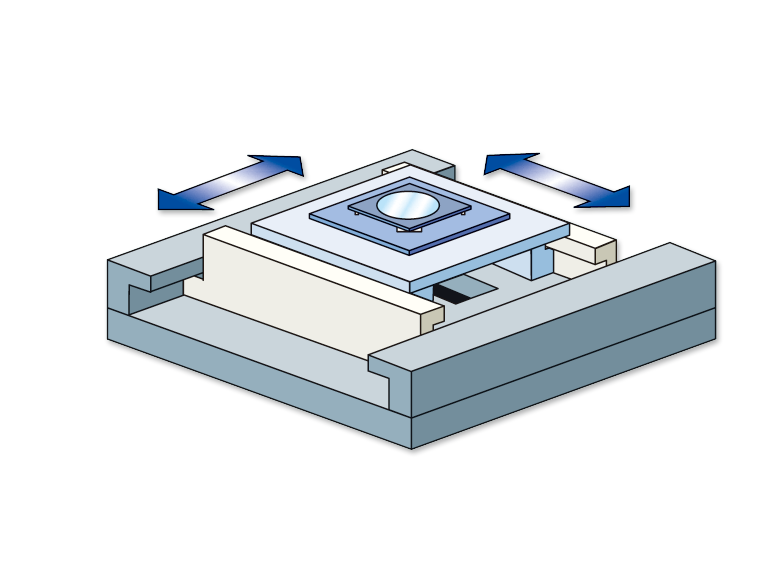
Useful for precise micro positioning, such as those required in semiconductor equipment.
Drive System
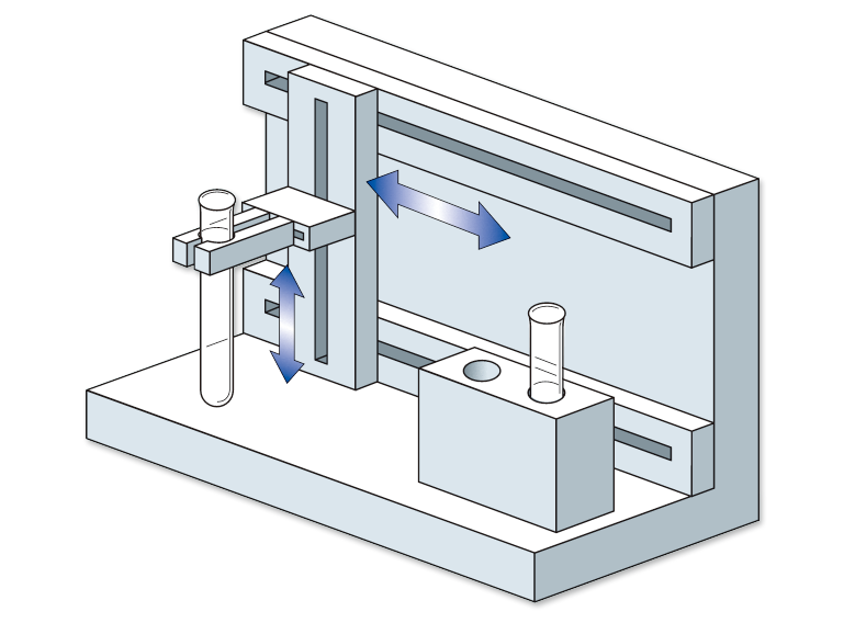
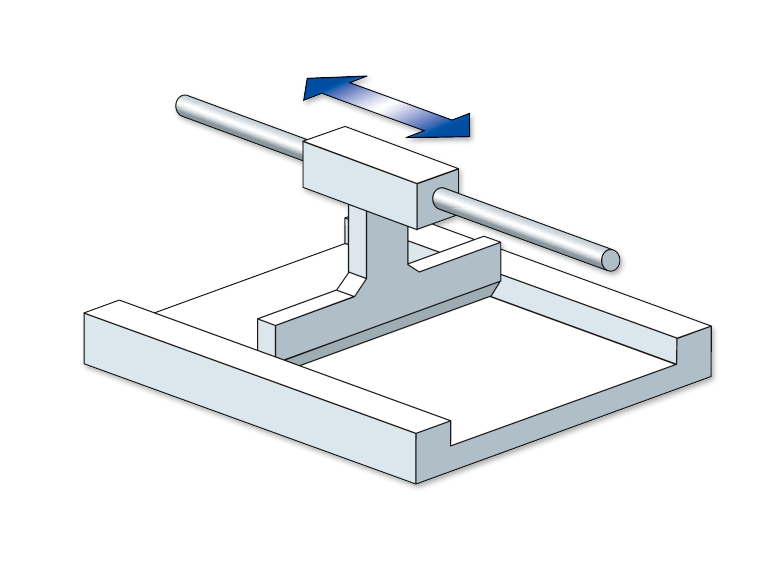
Single Drive System
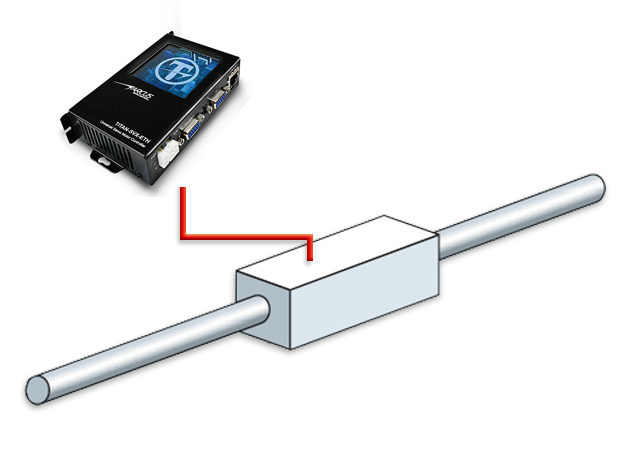
This is a basic drive system. The X and Y shafts can be used to create an X-Y stage.
Multi-Drive System
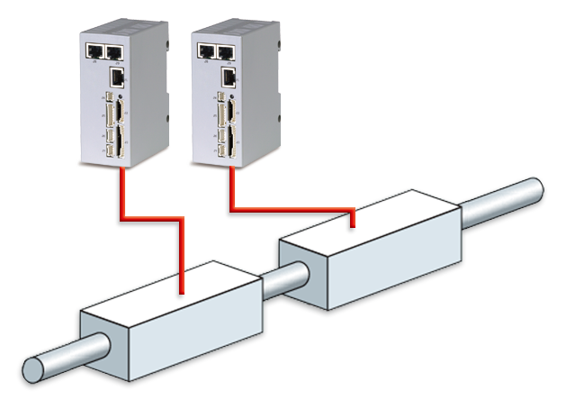
Multiple forcers can be used with a single shaft to support complex movements required by of some applications.
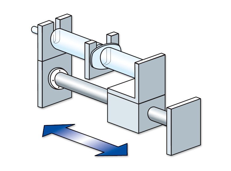
Tandem Drive System
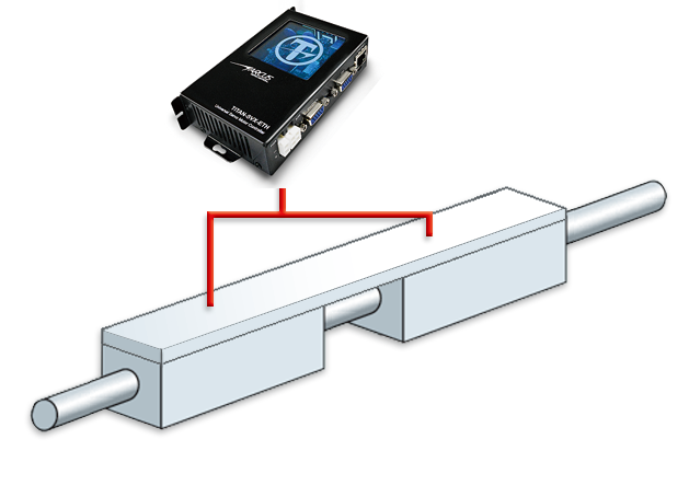
Two or more forcers can be used on the same shaft to multiply the thrust.
Parallel Drive System
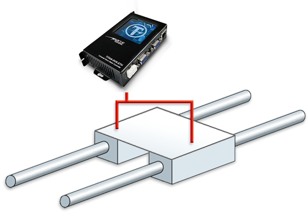
Linear Shaft Motors can be used in parallel (two or more forcers and two or more shafts connected to the same load), to achieve large thrusts for moving heavy objects.